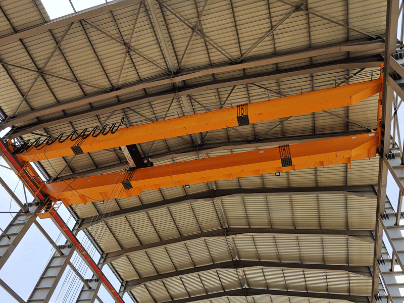
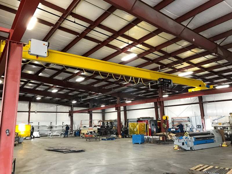
The bridge crane is a type of crane used in industrial environments. The overhead crane consists of parallel runways with a traveling bridge spanning the gap. A hoist, the lifting component of a crane, travels along the bridge. Unlike mobile or construction cranes, overhead cranes are typically used in manufacturing or maintenance applications where efficiency or downtime is a critical factor. The following will introduce some safe operating procedures for overhead cranes.
(1) General requirements
Operators must pass the training examination and obtain the “gantry crane driver” (code-named Q4) certificate before they can start working (hoisting machinery ground operators and remote control operators do not need to obtain this certificate and will be trained by the unit themselves) . The operator must be familiar with the structure and performance of the crane and should strictly abide by the safety regulations. It is strictly prohibited for patients with heart disease, patients with fear of heights, patients with high blood pressure, and patients with pornography to operate. Operators must have good rest and clean clothes. It is strictly forbidden to wear slippers or work barefoot. It is strictly prohibited to work under the influence of alcohol or when tired. It is strictly prohibited to answer and make calls on mobile phones or play games while working.
(2) Applicable environment
Working level A5; ambient temperature 0-400C; relative humidity not greater than 85%; not suitable for places with corrosive gas media; not suitable for lifting molten metal, toxic and flammable materials.
(3) Lifting mechanism
1. Double-beam trolley type overhead crane: The main and auxiliary lifting mechanisms are composed of (variable frequency) motors, brakes, reduction gearboxes, reels, etc. A limit switch is installed at the end of the drum shaft to limit the lifting height and depth. When the limit is activated in one direction, the lifting can only move in the opposite direction of the limit. Frequency conversion control hoisting is also equipped with a deceleration limit switch before the end point, so that it can automatically decelerate before the end limit switch is activated. There are three gears for lowering the non-frequency control motor hoisting mechanism. The first gear is reverse braking, which is used for slow descent of larger loads (above 70% rated load). The second gear is single-phase braking, which is used for slower lowering. It is used for slow descent with small loads (below 50% rated load), and the third gear and above are for electric descent and regenerative braking.
2. Single beam hoist type: The lifting mechanism is an electric hoist, which is divided into fast and slow gears. It consists of motor (with cone brake), reduction box, reel, rope arranging device, etc. The cone brake is adjusted with an adjusting nut. Rotate the nut clockwise to reduce the axial movement of the motor. Every 1/3 turn, the axial movement is adjusted accordingly by 0.5 mm. If the axial movement is greater than 3 mm, it should be adjusted in time.
(4) Car operating mechanism
1. Double-beam trolley type: The vertical involute gear reducer is driven by an electric motor, and the low-speed shaft of the reducer is connected to the driving wheel mounted on the trolley frame in a centralized drive manner. The electric motor adopts a double-ended output shaft, and the other end of the shaft is equipped with a brake. Limits are installed at both ends of the trolley frame. When the limit moves in one direction, the lifting can only move in the opposite direction of the limit.
2. Single-beam hoist type: The trolley is connected to the lifting mechanism through a swing bearing. The width between the two wheel sets of the trolley can be adjusted by adjusting the pad circle. It should be ensured that there is a gap of 4-5 mm on each side between the wheel rim and the lower side of the I-beam. Rubber stops are installed at both ends of the beam, and the rubber stops should be installed at the passive wheel end.


